Gate Controller
Board Specs
Complete hardware documentation for two gate automation controller boards — every IC, terminal, relay, and configuration parameter mapped and explained.
Board Overview
A 24V DC swing gate automation board driving up to two motors via relay H-bridges. Supports remote control, swipe card, IR safety sensors, and programmable timing via 7-segment display.
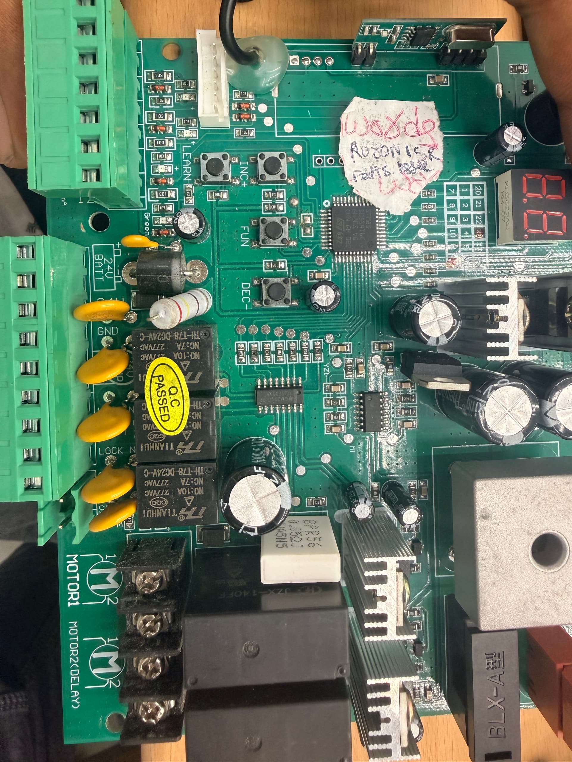
Power Supply
24V DC main input with 24V backup battery terminal. Regulated 12V output (200mA) for accessories. Internal 5V/3.3V rails for logic.
Dual Motor Output
MOTOR1 (primary arm) + MOTOR2 with programmable delay for dual-swing gates. H-bridge relay pairs reverse polarity for open/close direction.
Input Interfaces
433MHz remote receiver, swipe card reader (Wiegand), IR safety beam, 1SIDE/2SIDE triggers, and LEARN button for remote pairing.
Display & Programming
2-digit 7-segment LED display (KD3622AU driver). INC+, FUN, DEC- buttons for configuring timing, sensitivity, and operating modes.
Terminal Pinout
Green screw terminal block — low-voltage I/O
| Pin | Label | Function | Notes |
|---|---|---|---|
| 1 | 2SIDE | Two-side operation trigger | Opens both gate leaves |
| 2 | COM | Common ground | Shared ground reference |
| 3 | 1SIDE | One-side operation trigger | Opens primary leaf only |
| 4 | SWIPE CARD | Card reader input | Wiegand-compatible |
| 5 | COM | Common ground | Second ground reference |
| 6 | IR | Infrared safety sensor | Active-low, blocks closing |
| 7 | 12V | 12V power output | Max 200mA for accessories |
Motor & Power Terminals
| Terminal | Pins | Function |
|---|---|---|
| MOTOR1 | 1, 2 | Primary gate arm — polarity determines open/close direction |
| MOTOR2 (DELAY) | 1, 2 | Secondary arm with programmable delay for dual-swing gates |
| 24V BATT | +, − | Backup battery input (24V DC) |
Component Analysis
Every major IC and component on the swing gate board — role, specifications, and placement.
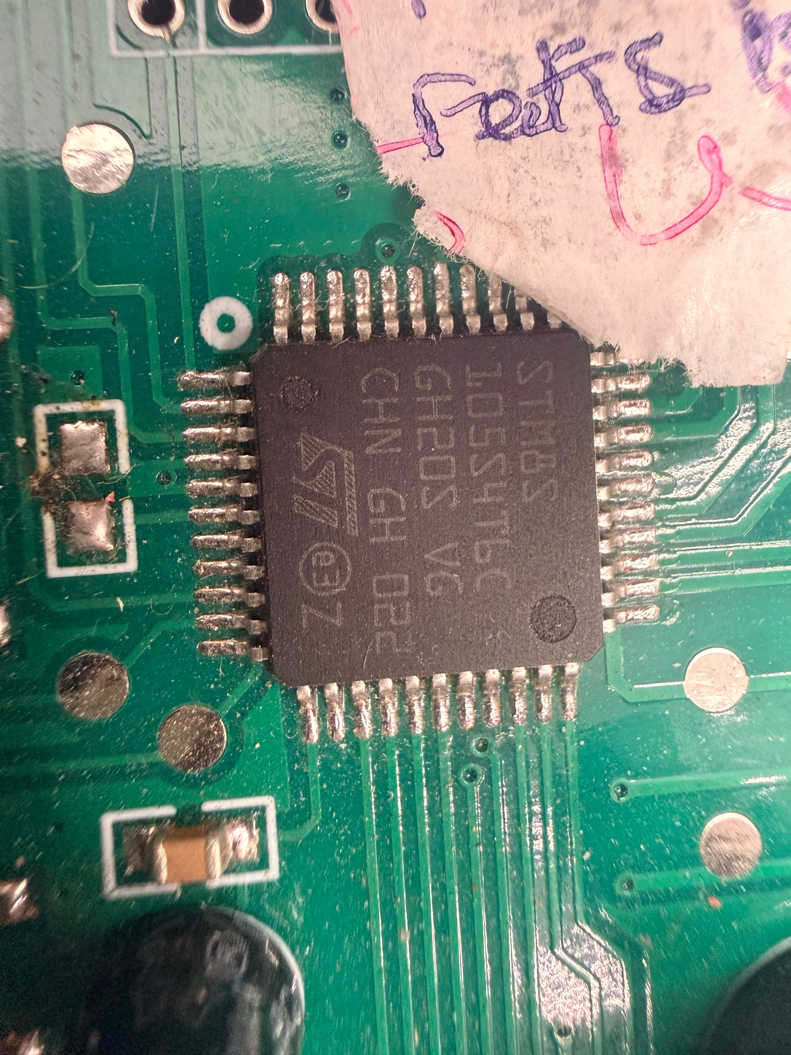
STM8S105S4T6C
The brain — runs all gate logic including motor timing, remote decoding, safety interlocks, and display control.
- ▸16 KB Flash / 2 KB RAM / 1 KB EEPROM
- ▸LQFP-44 package, 16 MHz clock
- ▸Programmable via SWIM (ST-LINK)
- ▸Built-in ADC, UART, SPI, I2C, Timers
- ▸Operating: 2.95V – 5.5V
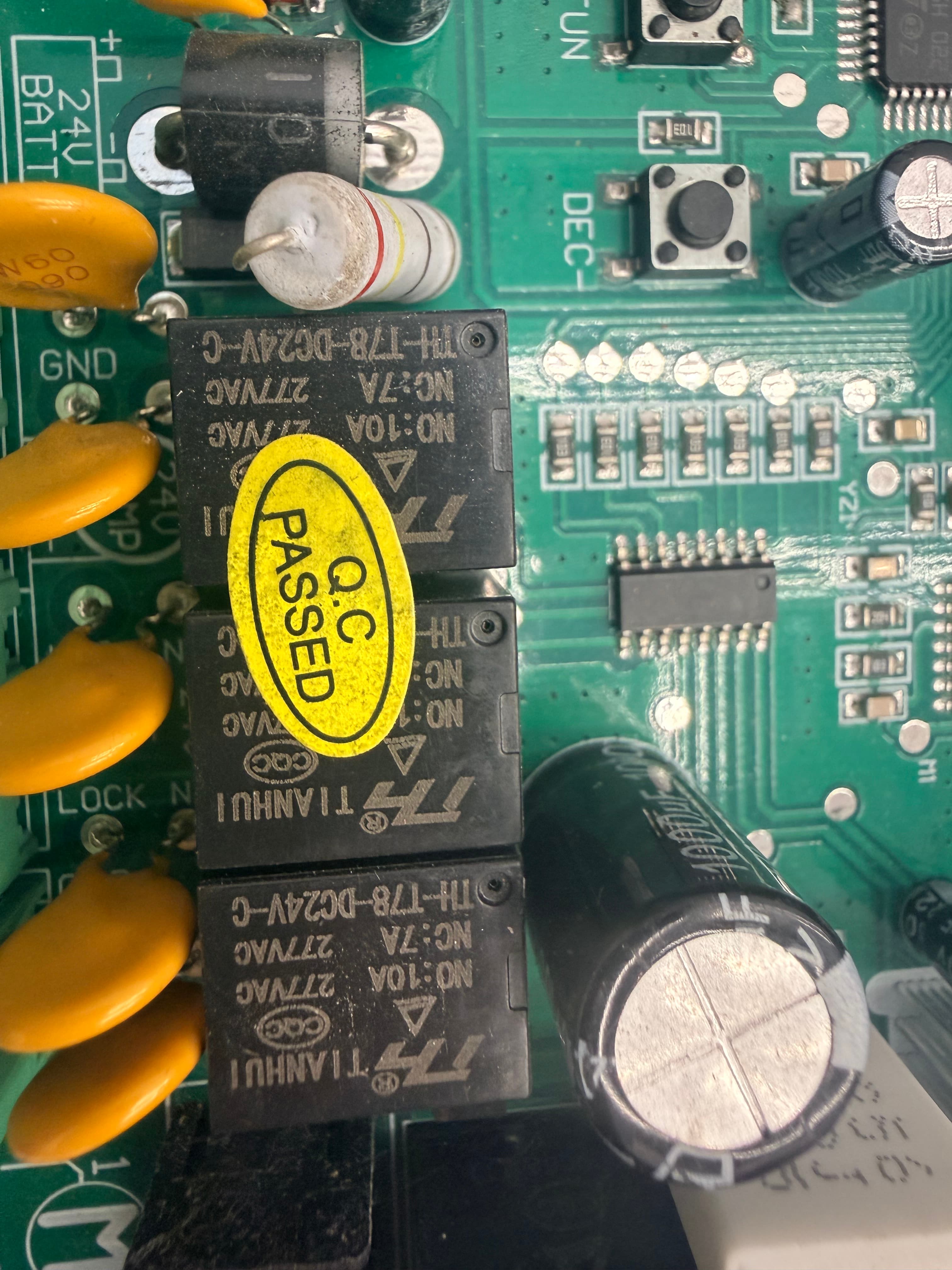
Tianhui TH-T78 Relays (×4)
Four relays form two H-bridge circuits — one per motor. They reverse 24V DC polarity to control gate open/close direction.
- ▸Coil: 24V DC
- ▸NO: 10A / NC: 7A @ 277VAC
- ▸Model: TH-T78-DC24V-C
- ▸2 relays per motor (H-bridge pair)
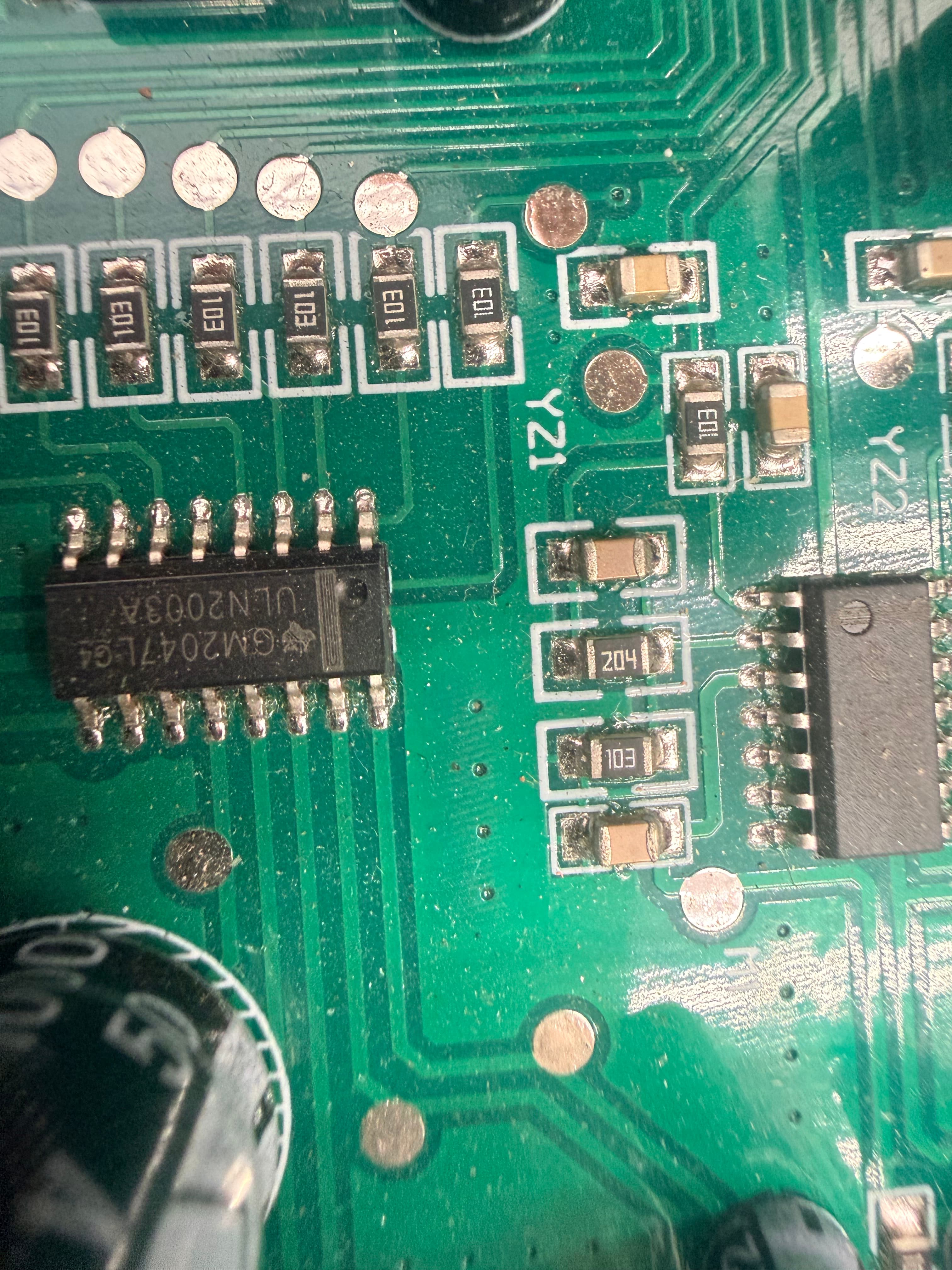
ULN2003A
7-channel Darlington transistor array bridging MCU GPIO pins to relay coils. Built-in flyback diodes protect against coil voltage spikes.
- ▸7 Darlington pairs, 500mA/ch
- ▸50V max output voltage
- ▸3.3V/5V logic compatible
- ▸Manufacturer: Texas Instruments
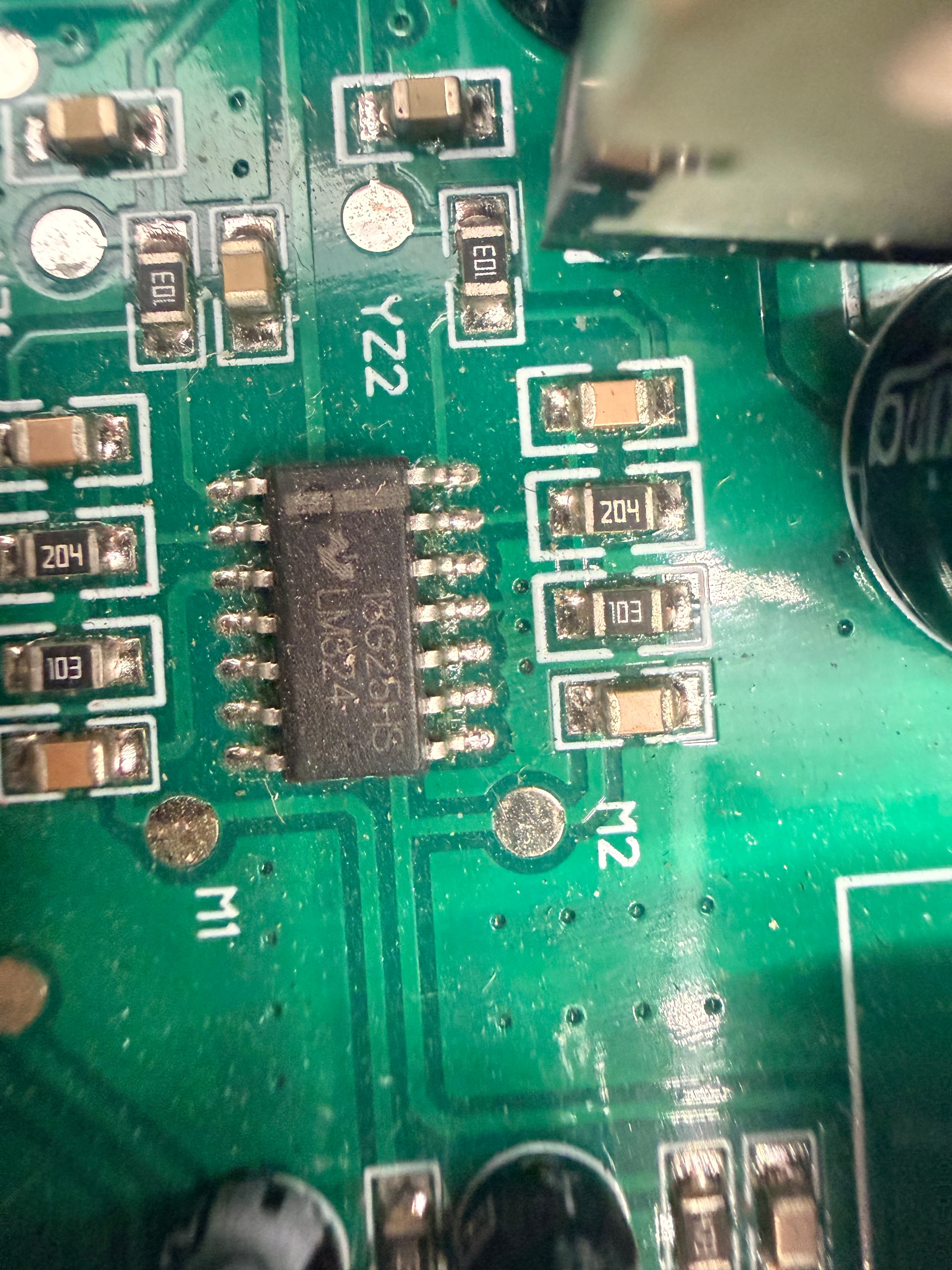
LM324 Quad Op-Amp
Quad operational amplifier for analog signal conditioning — processes IR sensor input and motor current sensing for overload protection.
- ▸4 independent op-amps
- ▸Supply: 3V – 32V single
- ▸Quiescent: ~0.7mA per amp
- ▸SOIC-14 package (TI)
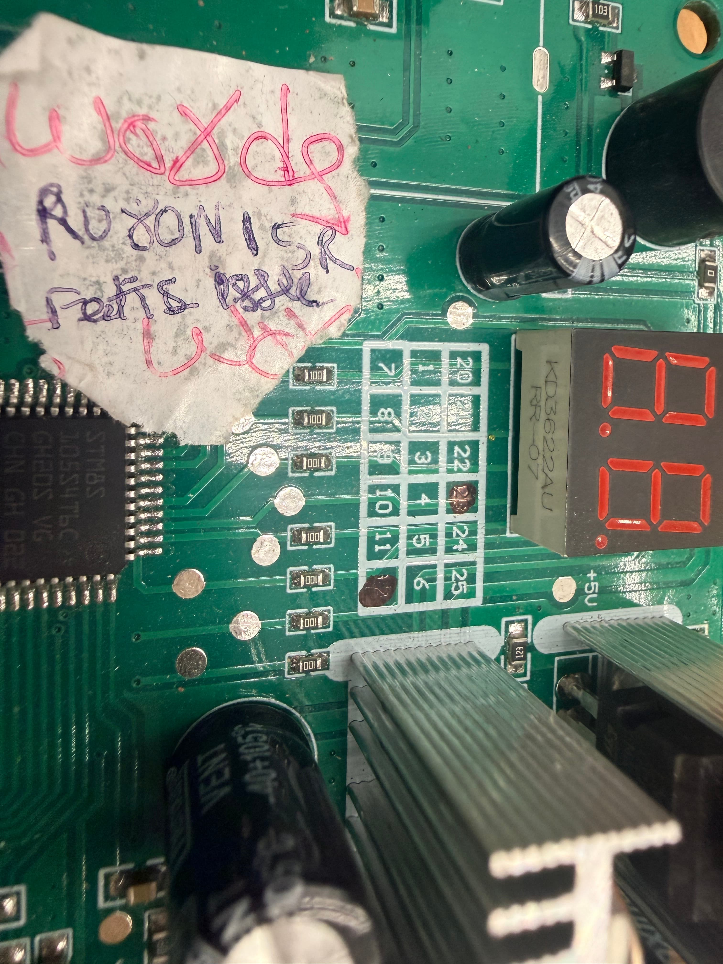
KD3622AU RR-07
Drives the 2-digit 7-segment LED display. MCU sends serial data; this IC handles segment multiplexing and current driving.
- ▸2-digit 7-segment driver
- ▸Serial data interface
- ▸Displays codes 00–99
- ▸Status, error, and config display
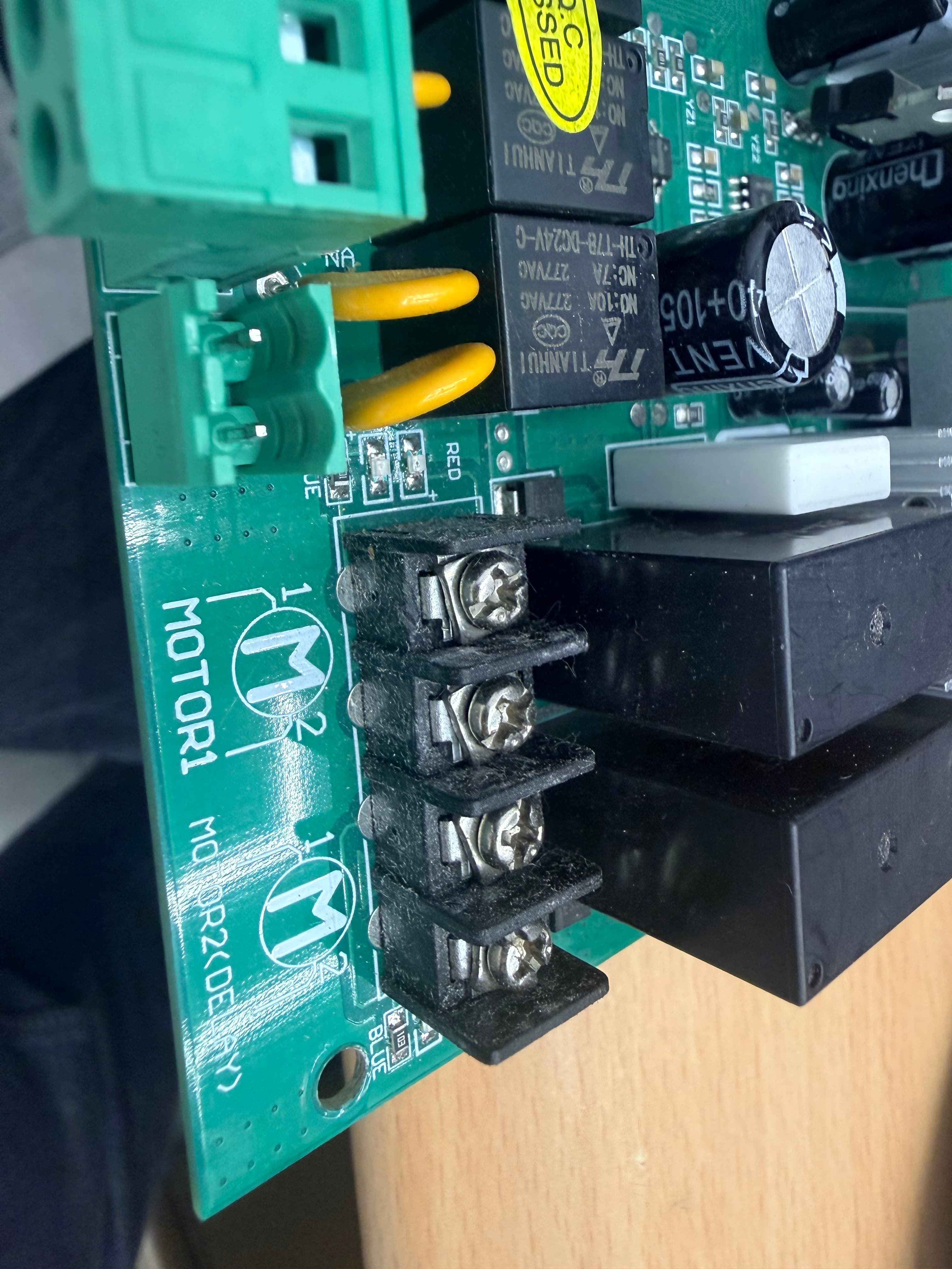
Motor Screw Terminals
Heavy-duty terminals for MOTOR1, MOTOR2 (DELAY), and 24V backup battery. Relay H-bridge reverses polarity at these terminals.
- ▸MOTOR1: Terminals 1 & 2
- ▸MOTOR2 (DELAY): Terminals 1 & 2
- ▸24V BATT: 2-pin backup input
- ▸Secure screw-clamp connection
System Signal Flow
How inputs are processed, decisions are made, and motors are driven through the complete signal chain.
Signal Input
User triggers the gate via remote, swipe card, or wired button. IR sensor provides safety feedback — blocks closing when beam is broken.
Logic Processing
STM8S runs the state machine: idle → opening → opened → closing → closed. Manages timing, delay, and obstacle detection via LM324 feedback.
Relay Driving
MCU outputs logic signals to ULN2003A Darlington array. Each channel sinks ~100mA to energize relay coils. Built-in flyback diodes handle inductive spikes.
Motor Control
4 relays form two H-bridges. Relay A1 ON + A2 OFF = forward. A1 OFF + A2 ON = reverse. Both OFF = stopped. Polarity reversal at terminals sets direction.
PKM-C022-2 Actuator
DC24V heavy-duty linear actuator arm for swing gates. Dual-arm setup with push-pull rod mechanism, manual key release, and IP55 weather protection.
Technical Specifications
| Parameter | Value |
|---|---|
| Model | PKM-C022-2 |
| Input Power | AC 110V/220V ± 10% |
| Motor Voltage | 24V DC |
| Power (per arm) | 60W |
| Actuator Speed | 2.4 cm/s |
| Max Actuator Travel | 400mm |
| Max Single-Leaf Weight | 350 KG |
| Max Single-Leaf Length | 3.8 meters |
| Max Gate Opening Angle | 110° |
| Protection Class | IP55 (dust & water jet proof) |
| Ambient Temperature | −22°C ~ +55°C |
Standard Parts
Optional Accessories
Weight / Length Compatibility
Supported combinations for a single leaf — ✓ = recommended, — = not recommended
| Gate Weight | 1.5m | 2.0m | 2.6m | 3.2m | 3.8m |
|---|---|---|---|---|---|
| 350 KG | ✓ | — | — | — | — |
| 300 KG | ✓ | ✓ | — | — | — |
| 250 KG | ✓ | ✓ | ✓ | — | — |
| 200 KG | ✓ | ✓ | ✓ | ✓ | — |
| 150 KG | — | ✓ | ✓ | ✓ | ✓ |
| 100 KG | ✓ | ✓ | ✓ | ✓ | ✓ |
Pull or Push Install
Two mounting modes: pull-to-open (inward) or push-to-open (outward). Bracket position determines the mode — refer to dimension chart for A/B/D values.
Post Bracket Setup
Bolt post bracket + post pivot bracket at gate hinge height. Height must match exactly — mismatch causes arm bending and motor strain.
Arm Attachment
Attach gate bracket and post bracket assembly to opener via clevis pins. Secure with hairpin clips. Repeat for second arm on dual-gate setups.
Manual Release
Insert release key and turn 90° clockwise to disengage motor. Arm extends/retracts freely by hand for emergency or power-out operation.
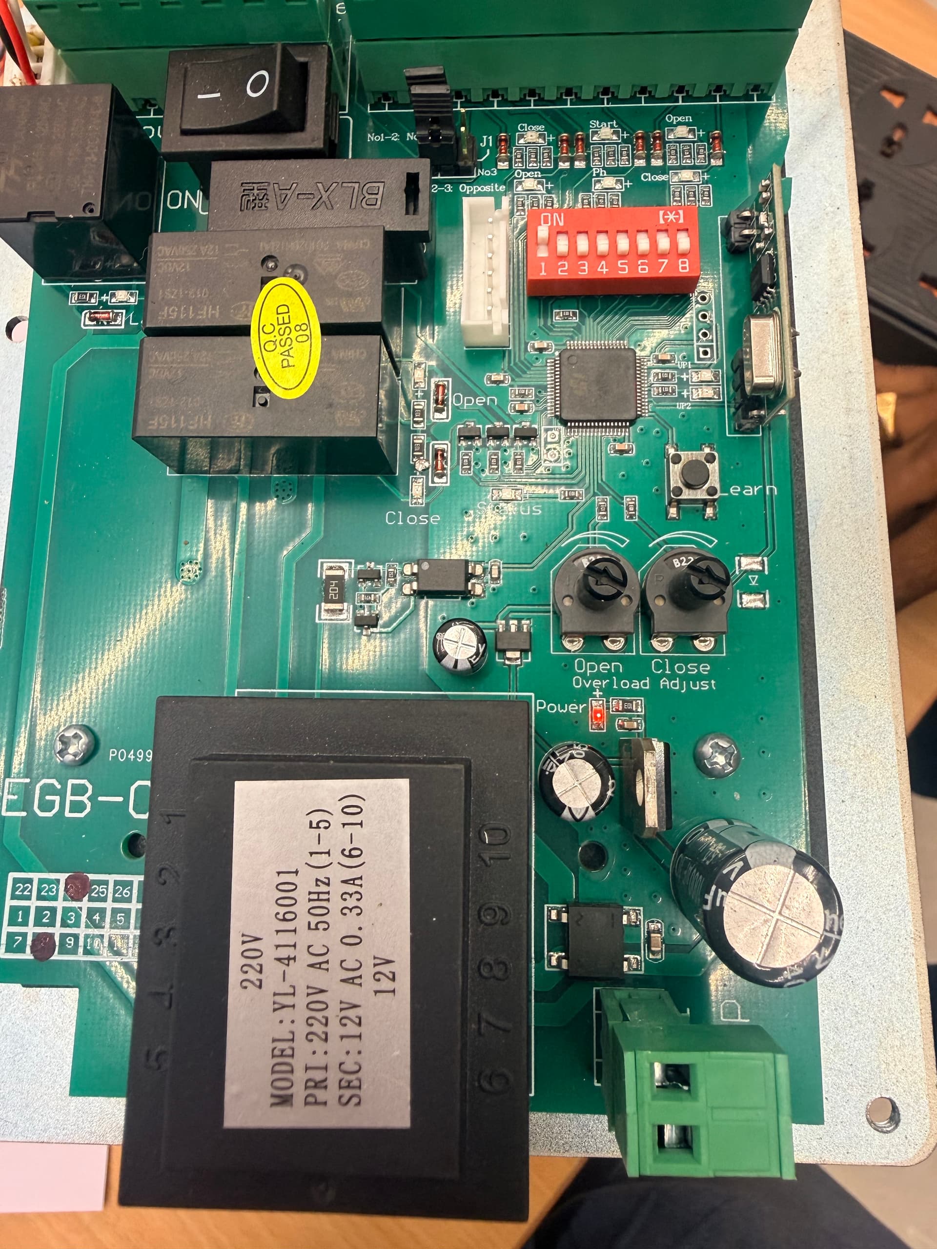
Board Overview
An AC-powered sliding gate controller board (Model EGB-02). Operates on 220V AC mains with an onboard transformer, featuring DIP switch configuration, potentiometer tuning, and relay-based motor control with soft start/stop.
Power Supply
220V AC mains input via KL-50-503 transformer (240V/50Hz, 10V/5W output). Model YL-411600I primary 220V AC, secondary 12V AC. Internal regulation to 12V DC for logic and relays.
8-Position DIP Switch
Hardware configuration via red DIP switch: DIR, BRAKE, REMOTE, BLOCKBACK, AUTOCLOSE (×2), LIMIT, and SOFT start/stop modes.
3 Potentiometers
Analog tuning knobs: FORCE (motor torque), SLOWING (deceleration curve), and TIME/BLOCK (auto-close delay / obstacle block time).
Output Terminals
Labeled outputs: Open, Close, Status, Power. Additional: OPLM (open limit), CLR (clear), DEF (default), PED (pedestrian), OSC (oscillator/lamp).
DIP Switch Configuration
8-position red DIP switch — ON enables, OFF disables
Potentiometer Controls
Output & Signal Terminals
| Terminal | Function | Description |
|---|---|---|
| Open | Open trigger input | Momentary contact to trigger gate open cycle |
| Close | Close trigger input | Momentary contact to trigger gate close cycle |
| Status | Status output | Logic output indicating current gate state |
| Power | Power indicator | Board power status output |
| OPLM | Open limit | Open limit switch input — stops motor at fully open |
| CLR | Clear / Reset | Clears current cycle or resets fault |
| DEF | Default | Factory default restore input |
| PED | Pedestrian mode | Partial open for pedestrian access |
| OSC | Lamp / Flash output | Drives warning lamp during gate movement |
Component Analysis
Every major IC, relay, and module on the sliding gate controller board.
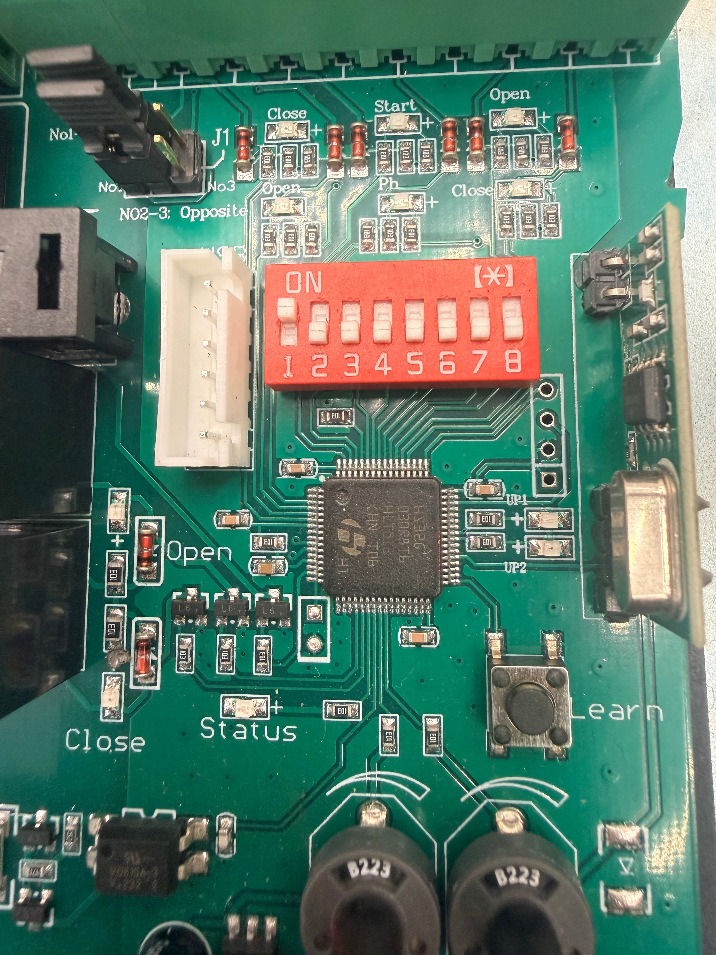
Main MCU & DIP Switch
Central MCU (LQFP package) handles all gate logic. The 8-position red DIP switch provides hardware-level configuration without firmware changes.
- ▸QFP-packaged microcontroller
- ▸8-bit DIP switch for mode selection
- ▸White JST connector for external interface
- ▸Board silk: Open, Close, Status labels
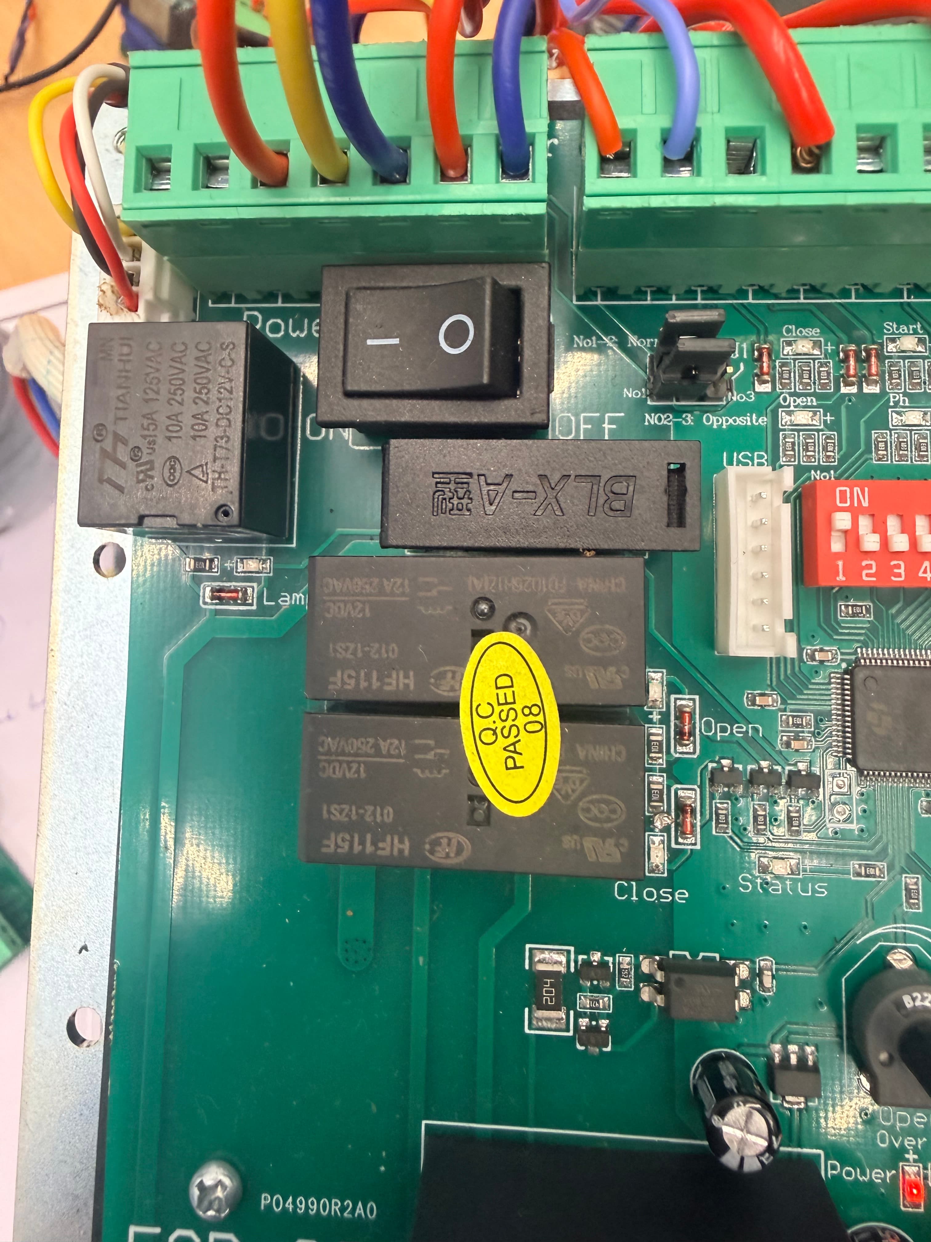
HF115F Relays + Power Switch
Two HF115F signal relays for motor direction control plus a main power rocker switch (BLX-A). The relays switch motor winding connections for forward/reverse.
- ▸HF115F: 12V coil, 8A/250VAC contacts
- ▸BLX-A rocker switch: main AC on/off
- ▸Q.C. PASSED 08 inspection sticker
- ▸Colored wiring to screw terminals
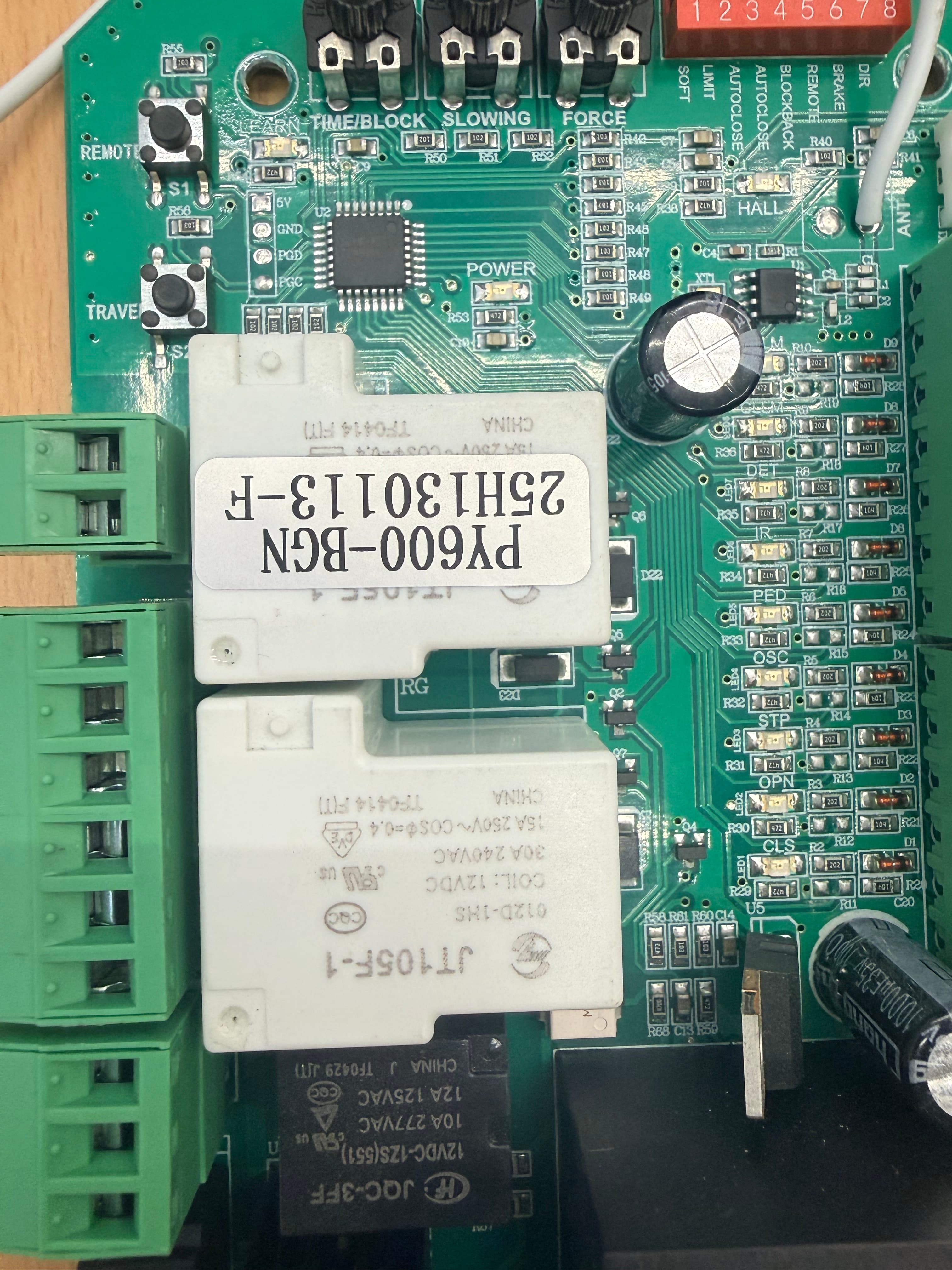
PY600-BGN-F & JT105F-1
PY600-BGN-F transformer module for power conversion. JT105F-1 is a heavy-duty 30A relay for main motor power switching — handles the high current draw of sliding gate motors.
- ▸PY600-BGN-F: power transformer module
- ▸JT105F-1: 30A/240VAC power relay
- ▸Coil: 12VDC
- ▸Green screw terminals for motor output
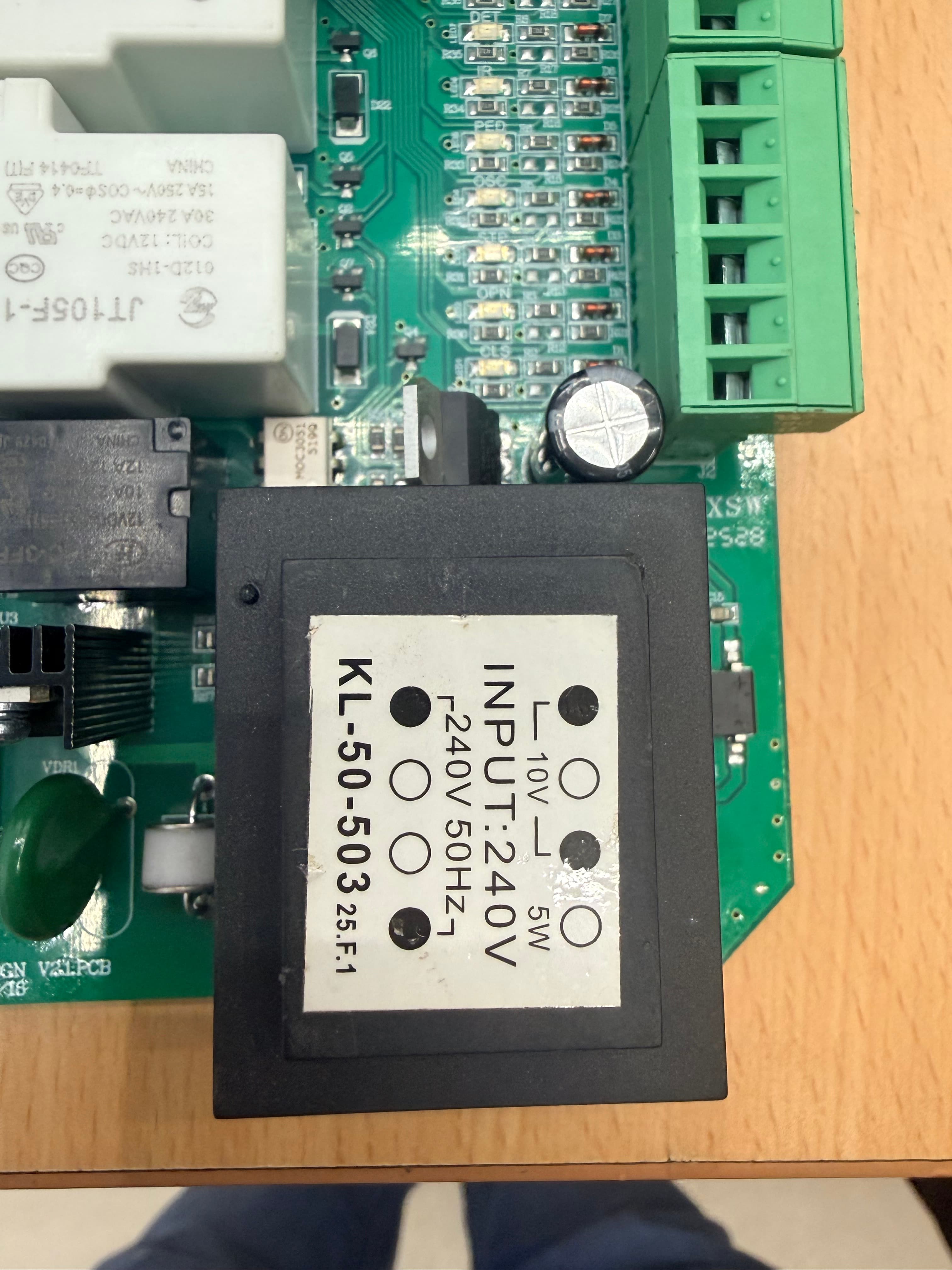
KL-50-503 Transformer
PCB-mount encapsulated mains transformer. Converts 240V 50Hz AC to 10V AC at 5W for the board's internal power supply. Feeds the rectifier/regulator circuit for 12V DC rails.
- ▸Input: 240V AC 50Hz
- ▸Output: 10V AC, 5W
- ▸Model: KL-50-503 25.F.1
- ▸Encapsulated, PCB-mount
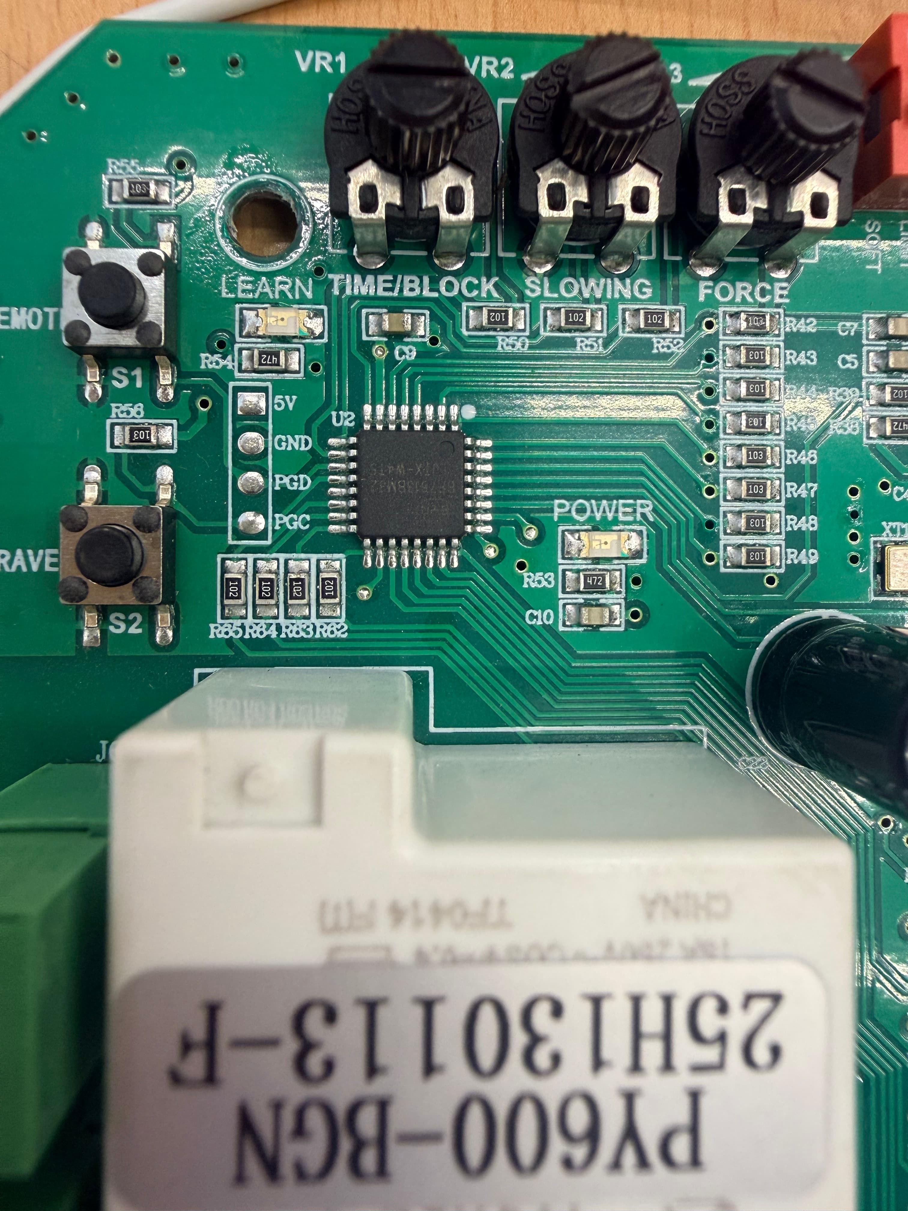
Pots, Buttons & MCU
Three potentiometers (FORCE, SLOWING, TIME/BLOCK) for analog adjustment. S1 (LEARN/REMOTE) and S2 (SAVE) push buttons. Secondary MCU visible with LEARN, GND, 5V, P4D pin labels.
- ▸VR1: FORCE, VR2: SLOWING
- ▸S1: LEARN/REMOTE pairing button
- ▸S2: SAVE settings button
- ▸MCU pins: GND, 5V, P4D (programming)
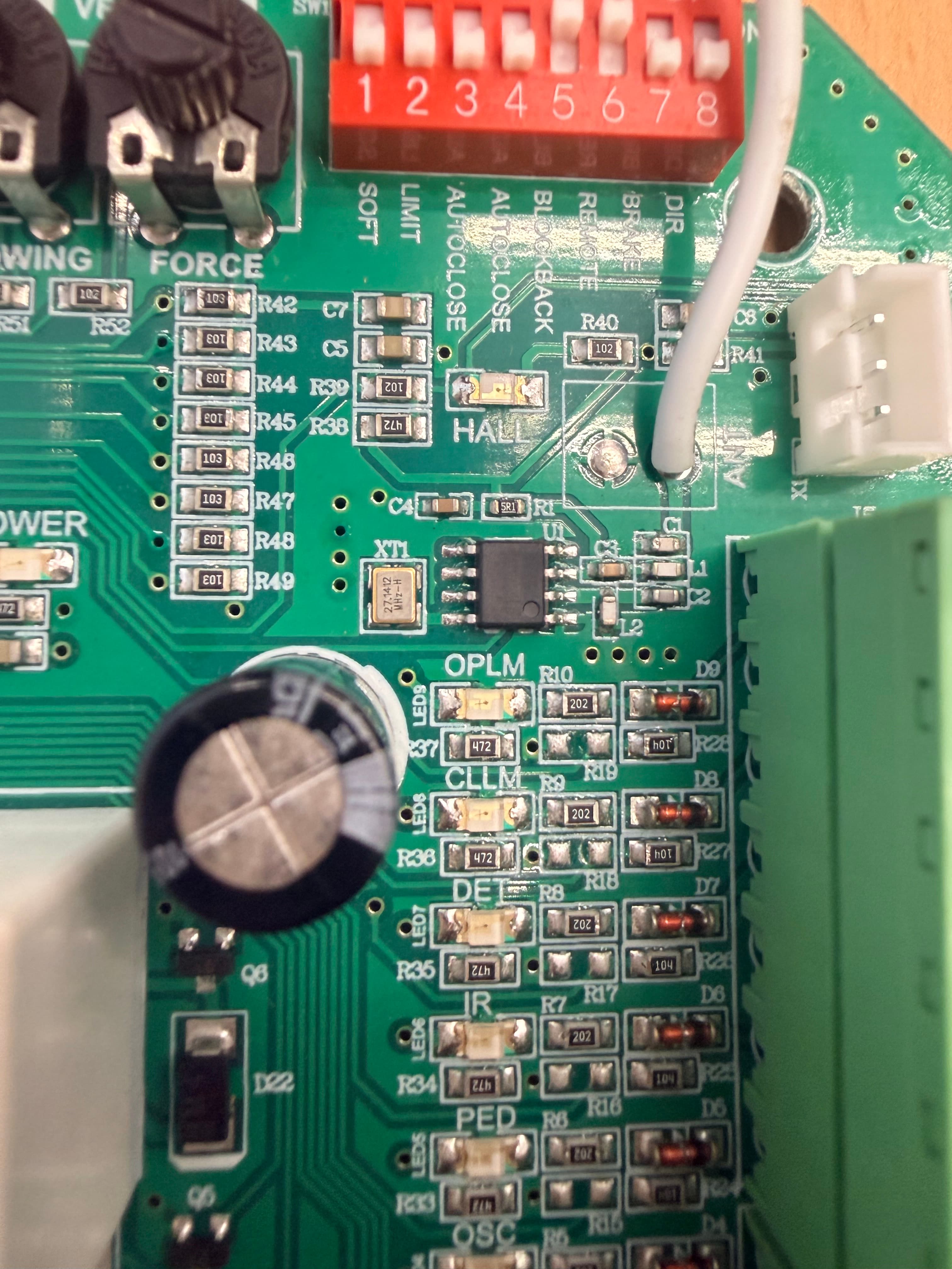
Hall Sensor IC & DIP Switch Area
SOIC-8 IC near the HALL label — likely a Hall-effect sensor interface for motor position/speed feedback. White JST connector for external Hall sensor cable.
- ▸HALL: Hall-effect sensor input
- ▸SOIC-8 interface IC
- ▸JST connector for external sensor
- ▸DIR through SOFT DIP labels visible
System Signal Flow
AC mains power path, motor control via relay + triac, and sensor feedback loop.
AC Power In
220V AC mains enters through the rocker switch. The KL-50-503 transformer steps it down to 10V AC, which is rectified and regulated to 12V DC for the board’s logic and relay coils.
Configuration
The 8-position DIP switch sets operating modes (direction, braking, auto-close, limits, soft-start). Three potentiometers fine-tune force, slowing distance, and timing.
Motor Control
Two HF115F relays select motor direction (forward/reverse). The JT105F-1 30A relay handles main motor power. The MOC3063 opto-triac provides isolated AC switching for soft start/stop ramping.
Feedback Loop
Hall-effect sensor on the motor provides real-time position and speed feedback. Limit switch inputs (OPLM) stop the motor at end positions. BLOCKBACK mode reverses on obstacle detection.
SL600AC / S-AZSL Series
AC-powered sliding gate opener units with gear-rack drive. Available in 600 KG and 1000 KG variants, supporting gates up to 12 meters. Spring or magnetic limit switches, manual key release, and gear-rack propulsion.
Model Comparison
Three sliding gate motor models — * intelligent control board supports 40 remotes
| Parameter | SL600AC | S-AZSL600 | S-AZSL1000 |
|---|---|---|---|
| Power Supply | 110V/220VAC | 220VAC/50Hz | 220VAC/50Hz |
| Motor Power | 280W | 280W | 380W |
| Gate Moving Speed | 13 m/min | 13 m/min | 13 m/min |
| Max Loading Weight | 600 KG | 600 KG | 1000 KG |
| Max Gate Length | 8m | 12m | 12m |
| Remote Distance | ≥ 30m | ≥ 30m | ≥ 30m |
| Remote Frequency | 433.92 MHz | 433.92 MHz | 433.92 MHz |
| Working Noise | ≤ 58 dB | ≤ 56 dB | ≤ 58 dB |
| Working Duty | S2, 15min | S2, 20min | S2, 20min |
| Max Remote Pairing | 25 / 40* | 25 / 40* | 25 / 40* |
| Working Temperature | −20°C ~ +70°C | −20°C ~ +70°C | −20°C ~ +70°C |
| Limit Switch | Spring / Magnetic | Spring / Magnetic | Spring / Magnetic |
| Package Weight | 9.4 KG | 10.10 KG | 10.18 KG |
Standard Parts
Optional Accessories
Gear Rack Drive
Motor output gear meshes with galvanized or nylon gear rack mounted along the gate. The rotating gear propels the gate along its track at 13 m/min.
Limit Switches
Spring limit switches (mechanical) or magnetic limit switches stop the motor at open and close positions. Magnets mount on the gear rack; sensors are inside the motor housing.
Manual Release
Insert key and turn the manual release bar 90°. The output gear disengages, allowing the gate to slide freely by hand during power outage or emergency.
Safety & Accessories
Infrared photocell detects obstacles and halts closing. Optional alarm lamp, wireless keypad, and wired push-button provide flexible access control.